Sizing and Applying Sanitary Control Valves
Proper Cv sizing, positioner selection, and a real-world caramel system redesign that eliminated a pump and cut valve count in half.
Specifying a control valve by port size — matching it to the pipe diameter — is one of the most common mistakes in process design. The right approach starts with the flow coefficient.
The W68 series sanitary control valve is a versatile workhorse: it can provide backpressure on a centrifugal pump, throttle flow in a filling or blending application, or handle divert control with the W685 and W682 variants. But it performs correctly only when it’s been sized for the actual flow and pressure conditions of the application.
This post covers the fundamentals of Cv-based sizing, positioner selection, and ends with a real application case study that shows how the right valve configuration simplified an entire caramel processing system.
The Cv Sizing Formula
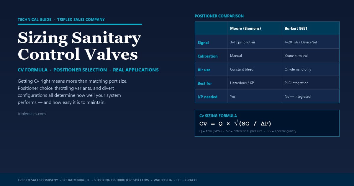
Flow coefficient (Cv) represents the volume of water (in gallons per minute) that will flow through a valve at a 1 psi pressure drop. It’s the universal sizing currency for control valves. For sanitary applications:
Note that differential pressure means inlet pressure minus outlet pressure across the valve — not system pressure. If your pump produces 80 psi and your downstream process operates at 50 psi, your ΔP across the valve is 30 psi, not 80.

For fluids with viscosity significantly different from water, a viscosity correction factor applies. For most dairy, beverage, and food processing fluids at process temperatures, water-like specific gravity is a reasonable starting assumption.
Sizing Principles: Operate Near 50% Stroke
The goal in control valve sizing is to operate the valve at approximately 50% stroke under normal conditions. This keeps the valve in the most linear, controllable part of its range. Operating at the extremes — nearly closed or nearly fully open — causes erratic behavior and makes precise flow control difficult or impossible.
Standard Cv stem options for the W68 are published in DS-1207. The 1.0″ and 1.5″ valves use a reduced orifice throttling stem design, making them well-suited to high-backpressure applications like RO membrane systems. Armoloy coating on the stem and seat is available for abrasive or erosive services.
Positioner Options: Moore vs. Burkert
The W68 is available with two positioner options, and the choice between them affects installation complexity, maintenance requirements, and integration with plant control systems.

The Burkert EP positioner integrates the I/P conversion function directly, meaning the separate I/P device required for the Moore positioner isn’t needed. In practice, this can reduce both panel footprint and ongoing maintenance. The auto-calibration feature is also meaningful in applications with vibration that would periodically throw off a Moore positioner.
The one area where the Moore positioner has an advantage is hazardous-location applications. Because it’s entirely mechanical (pneumatic in, pneumatic out), it can be used in classified environments where the Burkert electronic positioner is not appropriate. A Class 1/Division 2 version of the Burkert 8681 is available, but confirm requirements with the customer’s safety officer before specifying.
Throttling Variants: W685 and W682
Standard single-seat throttling (W68) isn’t the only configuration. For applications that need to split or combine flow while maintaining throttle control, two divert variants reduce valve count:
Case Study: Caramel System Redesign
Caramel Processing System — Valve-Based Simplification
A confectionery processor was running a caramel recirculation and packaging supply system with a complex arrangement of pumps, isolation valves, and VFDs. The original design included a recirculation pump with isolation valves, a separate header and shutoff valve to direct flow to packaging, a second supply pump with its own isolation valves and VFD, and a flow meter on the packaging line.

Original System
- Two pumps (recirc + supply)
- Two VFDs
- Multiple isolation valves
- Separate header + shutoff valve
- Manual flow control
Redesigned System
- One pump (8 gpm)
- One VFD
- WR63 for pump protection + CIP divert
- W685 throttling divert valve
- Integrated PLC control with mass flow meter
The redesign removed the second pump entirely and replaced the header/shutoff valve combination with a single W685 throttling divert valve. The W685 was integrated with the packaging line mass flow meter and the pump VFD, allowing the 8 gpm pump to split flow evenly between the recirculation loop and the processing line — with the PLC managing the balance automatically.
A WR63 pressure relief valve replaced the isolation valves for pump protection and CIP divert. W73 valves were also incorporated for CIP/water/product separation at key points in the system.
The result: Significant reduction in installed component count, elimination of one pump and VFD, simpler PLC programming, and a system that’s easier to clean and maintain.
Control valve applications reward careful front-end engineering. The time spent calculating Cv, selecting the right positioner, and considering whether a divert variant simplifies the system pays off in a process that runs well and is easy to maintain. SPX Flow Applications Engineering is available to review sizing calculations and positioner selections on complex applications.
Need help sizing a control valve or evaluating a system redesign opportunity?
Contact Triplex →
