When Good Valves Go Bad
Real-world failure case studies from sanitary process systems — and what the evidence tells you about why things went wrong.
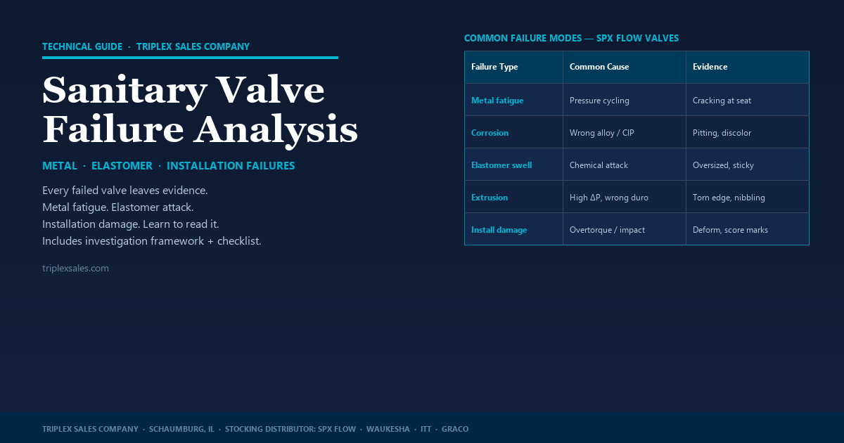
Valve failures rarely happen without a reason. Whether you’re looking at a cracked elastomer, a pitted body seat, or a stem that won’t move, the physical evidence — if you know how to read it — usually points directly at the cause. The hard part is asking the right questions and resisting the urge to replace the part without understanding why it failed.
What follows are real scenarios from the field. Each one illustrates a failure mode, what the physical evidence looked like, and what investigation revealed about the true cause.
Metal Component Failures

High-pressure filtration applications — RO systems in particular — are a known challenging environment for control valves. The combination of high pressure differentials, high velocity, and sometimes particulate-laden streams creates erosive conditions that can destroy wetted metal components in short order.
The damage pattern from velocity erosion is distinctive: a smooth, polished-looking wearing away of material, often most severe at the seat area and on the throttling stem where flow velocity is highest. Cavitation leaves a rougher, pitted surface with small craters that can look almost like sandblasting.
In severe cases, both the stem and the seat can fail in a matter of weeks rather than years. The valve body itself can also be affected depending on flow geometry.
Crevice corrosion in stainless steel is a localized attack that occurs at or immediately adjacent to the gap between two mating surfaces — classically at the seat-to-body interface in a valve. The corrosion mechanism involves chlorides becoming trapped at the crevice, where oxygen depletion creates an electrochemical cell that attacks the passive oxide layer on the 316L stainless.
In this case, a customer struggled for several years with what appeared to be a recurring corrosion problem. They questioned metal quality, process compatibility, chemical supplier, their CIP procedures, and piping layout. Every investigation came up empty.
The actual cause: city water with extremely high chlorine levels. The rinse water being used after CIP contained enough free chlorine to attack the metal at the seat crevice — damage that appeared to be from the cleaning chemical, but was actually from the rinse cycle intended to remove it.
Crevice corrosion first appears as pitting on the metal seat surface of the body. If the pits are appearing consistently at the seat interface rather than randomly across the wetted surface, suspect chloride concentration at that specific geometry.
Stainless-to-stainless contact under load is prone to galling — a form of severe adhesive wear where the surfaces bond under friction and then tear apart as motion continues. In extreme cases, the components can essentially fuse together, a phenomenon sometimes called cold welding or friction welding.
That’s what happened here: a customer running W72RS mix-proof valves in a challenging application with salts, sugars, acids, and abrasives present reported that stems couldn’t be removed from actuator pistons during maintenance. Investigation found the stems had galled so severely to the pistons that they required destructive removal — many major components had to be replaced across multiple valves.
The cause was straightforward: no thread lubricant. Never-Seez anti-seize compound is called out in SPX Flow maintenance documentation for a reason. Stainless threads under the mechanical load of a valve actuator, in a challenging process environment, will gall without it.
Handling and Installation Failures

A customer ordered D4 manifolds. During fabrication of the manifolds, the valve inserts were left on the shop floor — uncovered, in an active fabrication environment. A welding complication extended the fabrication timeline, leaving the inserts exposed for longer than intended.
At startup, every valve in the manifold showed excessive leaking from the housing flange. The inserts appeared intact. The seals looked fine on visual inspection. But the leak was consistent and severe across all valves.
The cause: Fabrication dust — grinding dust, weld spatter, metal fines — had contaminated the flange seal surfaces on the inserts while they sat on the floor. When the inserts were reinstalled into the bodies, the contamination prevented a water-tight seal at the flange interface.
A customer with DA4 mix-proof valves installed for several years began noticing leaking from the weep hole between housing seals. They replaced the seals repeatedly, thinking the seals were damaged — the leaking would stop briefly, then return.
The actual cause: chronic over-tightening of the flange bolts. Excessive torque compressed the seal carrier beyond specification, deforming it out of the correct dimensional range. Seals installed into an out-of-spec carrier would not seal correctly regardless of their condition.
The recurring repair cycle — replace seals, torque bolts down too tight, leak again — was masking the real problem and causing ongoing damage to the carrier itself.
After installation of new valves into a newly fabricated pipeline, orange-brown “rust” appeared in the valve bodies and on the stem and seat surfaces. The valves were stainless — rust wasn’t supposed to be possible. The customer suspected a material defect.
The actual cause: metal shavings and fabrication debris. The new piping hadn’t been thoroughly cleaned before startup. The debris — carbon steel shavings from cutting and grinding operations during fabrication — settled to the low points in the system, which happened to be the valves. Carbon steel oxidizes rapidly and the residue stained the stainless surfaces.
The stainless components themselves were not corroding or defective. The debris just happened to settle where it created the appearance of a valve failure.
Elastomer Failures: Reading the Evidence

Rubber and elastomeric components — diaphragms, seats, O-rings — are the most maintenance-intensive parts of a sanitary valve, and their failure modes are varied. The physical appearance of a failed elastomer usually tells you which failure mechanism was at work.
Several installations of W70 series mix-proof valves experienced an unusual symptom: after CIP, the lower stem would be slow to return to its normal position in the body bore, sometimes taking 10 minutes or longer. This triggered alarms and caused confusion about valve status during the post-CIP sequence.
The cause: maximum temperature ratings were being exceeded during part or all of the CIP cycle. Thermal expansion of the lower stem in the body bore was sufficient to cause binding. The stem would return to normal position — but only after enough cooling had occurred to allow thermal contraction.
A Framework for Failure Investigation

Troubleshooting a valve failure effectively requires asking the right questions — and sometimes asking the same question to multiple people, since answers often differ depending on who you ask. A mechanic may not know a CIP temperature changed. A CIP operator may not know a new chemical supplier was used.
Investigation Checklist
The SPX Flow troubleshooting guide in the back of every W-series IOM is a good structured starting point. SPX Flow Applications Engineering and your Triplex representative are also available to work through persistent or unusual failure patterns.
Quick Inspection Checklist — What Does the Seal Tell You?
The pattern across all of these cases is the same: failures that appeared to be valve problems turned out to be process, installation, or maintenance problems. A valve can only perform as well as the environment and procedures around it allow.
Troubleshooting a persistent valve issue and not sure where to look?
Talk to a Triplex specialist →
