Diaphragm Valve Basics: A Complete Guide for Sanitary Process Engineers
Everything you need to know about ITT Pure-Flo diaphragm valves — from body specs and surface finishes to diaphragm selection, dead leg elimination, and actuator sizing.
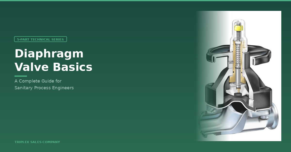
Anatomy of a Diaphragm Valve: What It Is and Why It Matters
If you work in pharmaceutical, biotech, food & beverage, or personal care manufacturing, you’ve almost certainly encountered diaphragm valves in your process piping systems. But what exactly makes them the valve of choice for high-purity applications? In this first post of our five-part series, we’ll break down the anatomy of a diaphragm valve and explain why it’s uniquely suited for sanitary process environments.
Three Components, One Valve
A diaphragm valve is fundamentally composed of three assemblies: the valve body (product contact), the diaphragm (product contact), and the topworks — sometimes called the bonnet or actuator (non-product contact). Understanding how these three elements work together is the key to specifying the right valve for your application.

The valve body provides the flow path and includes the weir — the raised ridge inside the valve that the diaphragm compresses against to shut off flow. The body also provides end connections (butt-weld, tri-clamp, or others) for tying into your process piping, as well as the bonnet flange that connects to the topworks above.


The diaphragm is the dynamic seal that enables and disables the flow path. It’s the only moving part in contact with the process fluid. When compressed against the weir, the valve is closed. When lifted, the valve is open. Diaphragms come in EPDM and PTFE varieties, each with different temperature ranges, chemical compatibility, and cycle life — we’ll cover these in detail in Part 4.
The topworks is the mechanism that moves the diaphragm. This can be a manual handwheel, a pneumatic actuator (fail-close, fail-open, or double-acting), or even an electric actuator. Switches and positioners can be added for feedback and control. We’ll dive into topworks in Part 5.
Why Choose a Diaphragm Valve?
Diaphragm valves dominate high-purity applications for three fundamental reasons:
Superior Cleanability: With no internal cavities, hold-up areas, or crevices, diaphragm valves eliminate places where product residue, bacteria, or contaminants can hide. This is critical in pharmaceutical and biotech environments where cleaning validation is a regulatory requirement.
Superior Drainability. The weir design, when the valve is properly installed, ensures maximum drainability — an essential factor in systems that must be fully evacuated between product changeovers or CIP (Clean-in-Place) cycles.
Application Versatility. Diaphragm valves handle a wide range of high-purity fluids: WFI (Water for Injection), purified water, buffer solutions, cell culture media, solvents, protein solutions, and more. They’re found in biotechnology, pharmaceutical, personal care, food & beverage, and brewery applications.
ITT Pure-Flo: Where They’re Made
ITT manufactures diaphragm valves at ISO 9001-2000 registered facilities worldwide. The Lancaster, PA facility is the Center of Excellence for both the EnviZion series and Pure-Flo series diaphragm valves, along with actuators and switches. Additional manufacturing is based in Obernkirchen, Germany, with ball valve production at Habonim, Israel, and a sales and manufacturing partnership with Tecnik Fluid Controls in India.
In the next post, we’ll take a deep dive into valve body specifications — materials, end connections, surface finishes, and configurations.
Valve Body Specifications: Material, Finish, and Configuration
The valve body is where engineering meets regulatory compliance. Every spec decision — from material grade to surface finish to end connection type — directly affects your system’s cleanability, corrosion resistance, documentation burden, and overall cost. In this post, we’ll walk through the four key specification areas for ITT Pure-Flo valve bodies.
End Connections
ITT Pure-Flo valves are available in fractional sizes (0.25″, 0.38″, 0.5″, 0.75″) and standard sizes (1″, 1.5″, 2″, 2.5″, 3″, 4″, and 6″). End connection types include butt-weld/auto-weld, tri-clamp, and others such as SMS and flange connections. Butt-weld is the most common in pharmaceutical piping because it eliminates external crevices, while tri-clamp connections offer serviceability where frequent disassembly is required.

Material
316L stainless steel is the industry standard for BioPharm applications. High-grade alloys such as C22, C276, and AL6XN are available for aggressive chemical environments. What matters equally is the method of construction:
Forged Bodies (-F)
Forged bodies are the standard for 2-way valves in sizes 0.5″ through 4″. Forging provides critical advantages for sanitary applications:
Key Advantages of Forged Bodies: Tri-certified to ASTM A182 316L, DIN17440, 1.4435, and BN2. Corrosion resistance is enhanced by low ferrite content (≤ 0.5%). Weldability is improved through controlled sulfur content per ASME BPE Table DT-3 (Sulfur: 0.005–0.017 max). No porosity issues. Both interior and exterior surfaces can be mechanically polished or electropolished.
ITT’s forging process has evolved from multi-piece welded construction to one-piece dedicated forgings. This evolution means a single CMTR (Certified Material Test Report) per body, shorter overall valve length, and compliance with ASME BPE fittings specifications for tangent length — all of which simplify documentation and reduce the total installed cost.
Wrought Bodies (-W)
Wrought construction (ASTM A479 316L) is used for block body valve configurations and 6″+ 2-way valves. Like forged bodies, wrought bodies have no porosity issues and can be mechanically or electropolished on both interior and exterior surfaces. Ferrite content is approximately 3%.

Surface Finish
Surface finish is measured as Ra (Roughness Average) in micrometres (µm) or microinches (µin). The Ra value is an average calculated from the peaks and valleys measured along a surface — the smoother the finish, the lower the Ra number.
Two polishing methods are used:
Mechanical Polish
Uses abrasives to smooth and polish the surface. Produces a linear surface lay pattern. Available at multiple Ra levels per the BPE finish specification chart.
Electropolish (EP)
Electrochemical process that removes metal from the surface (anodic dissolution). Improves corrosion resistance by removing iron residue and creating a chromium-rich oxide layer. Exposes pits, impurities, and defective welds. Reduces product adhesion and contamination buildup.
Why Circular Beats Linear on the Bonnet Flange
One detail often overlooked: the bonnet flange surface lay direction. A linear polishing pattern creates a potential leak path along the polishing lines — fluid can wick along the grooves. ITT addresses this with circular bonnet flange surfacing, which creates a concentric pattern that acts as a barrier to radial leak paths, providing a more reliable diaphragm seal.


Configuration
Beyond standard 2-way valves, ITT offers multi-valve fabrications and block body designs. These configurations are critical for minimizing dead legs in your piping system — a topic important enough to deserve its own post. That’s coming up next in Part 3.
Dead Legs, Block Bodies, and Why L/D Ratios Keep Engineers Up at Night
Dead legs are the silent enemy of sanitary process systems. Per ASME BPE-2022, a dead leg is “a space where system design and operating conditions result in insufficient process fluid flow, presenting a risk for particulate, chemical, or biological contamination.” When you install multiple valves side by side — which happens constantly in pharmaceutical and biotech manifold assemblies — dead legs become a major design consideration.
The FDA Guideline: L ≤ 6D
The FDA’s 1993 guideline established the first widely adopted dead leg standard: the length (L) of unused pipe should be no more than 6 times the diameter (D) of that pipe. For years, this was the benchmark. But the bioprocessing industry found that the 6D standard wasn’t sufficient for optimal cleanable and sterilizable systems.
The BPE Guideline: L/D = 2:1
ASME BPE tightened the standard to an L/D ratio of 2:1 — meaning the dead leg length should be no more than twice the pipe diameter. ASME BPE-2019 Section SD-3.11.1 is clear: the system designer and manufacturer shall make every attempt to eliminate system dead legs, and must identify where exceptions exist or where the 2:1 target cannot be met.
Bottom Line: If you’re designing to FDA guidelines (L ≤ 6D), you’re meeting the regulatory minimum. If you’re designing to BPE (L/D = 2:1), you’re meeting the industry standard for modern bioprocessing. But there’s a way to go even further.
Multi-Valve Fabrications
A multi-valve fabrication reduces dead legs by welding the second valve directly onto the D section of the first valve, eliminating the intermediate pipe run.

This gets you significantly better L/D performance than installing discrete valves side by side with pipe spools between them.
Block Bodies: Under 1D
Block body designs take dead leg reduction to the extreme. In an integrated block valve, the weir of the second valve is built directly into the weir of the first valve, achieving dead leg ratios of under 1D — effectively eliminating the dead leg entirely.

Here’s how the three approaches compare across common valve size combinations:
| Valve Arrangement | ½” × ½” | 1½” × ½” | 1″ × 1″ | 2″ × ½” |
|---|---|---|---|---|
| Sterile Access (SA) Array | 5.5 | 5.5 | 3.0 | 6.0 |
| GMP Array | 3.9 | 4.0 | 2.8 | 4.0 |
| Integral Sterile Access Block (ISG) | Under 1D | Under 1D | Under 1D | Under 1D |
The data speaks for itself. Even the GMP array — which uses closer valve spacing than a standard Sterile Access array — often can’t meet the BPE 2:1 target. The ISG block body achieves under 1D across the board.
Custom Block Designs
ITT pioneered integrated valve technology and offers custom block body designs tailored to specific customer applications or P&ID layouts. If your process requires multiple sample points, purge valves, or branched manifold configurations, a custom block design may be the most effective path to BPE compliance.


In the next post, we’ll shift from bodies to the dynamic seal at the heart of every diaphragm valve: the diaphragm itself.
EPDM vs. PTFE Diaphragms: Choosing the Right Seal for Your Process
The diaphragm is the working heart of a diaphragm valve — the only moving component in contact with your process fluid. Selecting the right diaphragm material isn’t just a parts decision; it directly affects your maintenance intervals, chemical compatibility, temperature capability, and failure mode behavior. ITT Pure-Flo offers two primary diaphragm families: EPDM elastomers and PTFE composites.

Diaphragm Specification Fundamentals
Regardless of material, every diaphragm must meet three requirements: chemical resistance to the process fluid, the ability to withstand SIP (Steam-in-Place) temperatures — typically 250°F — and compliance with FDA 21 CFR Part 177 and USP 28 Class VI (Chapters 87 and 88) certifications.
E1 EPDM — The Next-Generation Elastomer
| Specification | E1 EPDM |
|---|---|
| Sizes | 1/4″ to 4″ Pure-Flo |
| Liquid Temp Range | -4°F to 194°F (-20°C to 90°C) |
| Continuous Steam | -22°F to 285°F (-30°C to 140°C) |
| Intermittent Steam | -22°F to 302°F (-30°C to 150°C) |
| Approvals | FDA, USP Class VI, EMEA/410/01 TSE/BSE Compliant |
| Shelf Life | 6 years |
| Cure Method | Peroxide cured |
The E1 uses a high molecular weight EPDM elastomer — longer molecular chains mean greater strength, toughness, and chemical stress crack resistance. The material can be stretched further before rupturing and withstands greater impact stress. It’s also peroxide cured, animal-derived-ingredient free, and EMEA/410/01 TSE/BSE compliant. ITT reports 2–5× cycle life in hot water applications compared to the previous Gr17 generation, with comparable steam capability.
TME PTFE — The Long-Life Champion
| Specification | TME PTFE |
|---|---|
| Sizes | TME: 1/4″ to 4″ Pure-Flo; TMZ: 1/2″ to 2″ EnviZion |
| Temp Range | -4°F to 329°F (-20°C to 165°C) |
| Approvals | FDA, USP Class VI |
| Shelf Life | 10 years |
| Backing | Gr B1 EPDM backing cushion |
PTFE is chemically inert — there are essentially no chemical compatibility issues. It provides the longest life cycle of any available diaphragm material and features an advantageous failure mode compared to EPDM: when a PTFE diaphragm begins to fail, it tends to develop a slow weep rather than a sudden blowout, giving operators advance warning to schedule replacement.
Head-to-Head Comparison
Choose EPDM When
Your process operates below 194°F in liquid service.
Superior sealability is the priority.
Budget is a factor — EPDM is typically lower cost.
Your process fluid is chemically compatible with EPDM.
Choose PTFE When
You need broad chemical inertness across aggressive solvents or acids.
Your process temperatures exceed 194°F regularly.
Maximum diaphragm life and shelf life are priorities.
You want a predictable, gradual failure mode.
Identifying Your Diaphragms
Knowing what’s installed in your valves matters during maintenance. EPDM diaphragms are identified by markings on the front and back — look for the E1 designation and a date code. PTFE diaphragms use a 2-character or 4-character date code system: the first character represents the month (A=January through L=December), followed by the year digit(s), and optionally a batch number. For example, B171 means February 2017, Batch 1.

In our final post, we’ll cover everything above the diaphragm: topworks, actuator types, switches, positioners, and how to size your actuators correctly.
Topworks, Actuators, and Sizing: Controlling Your Diaphragm Valve
The topworks is the brain and muscle of a diaphragm valve. Whether you’re operating manually with a handwheel or running fully automated with pneumatic actuators, electronic switches, and positioners, the topworks assembly determines how reliably, how precisely, and how safely your valve responds to your process control system.


In this final post, we’ll cover manual and automated topworks, key accessories, actuator sizing, and the critical terminology you need to know.
Manual Topworks
Manual topworks come in two flavors: rising stem and rising handwheel. Both use a compressor that pushes down on the diaphragm when the handwheel is turned clockwise, closing the valve. A visual indicator (the stem position) tells operators at a glance whether the valve is open, closed, or somewhere in between.
Automated Topworks
Automated actuators use pneumatic pressure to open or close the valve, with spring return to provide a defined failure position. There are three types:
Fail Closed (FC) / Air-to-Open (ATO)
Pneumatic pressure on the bottom compartment opens the valve against spring force. If air supply is lost, the spring closes the valve automatically. This is the most common configuration in pharmaceutical and biotech applications, where a loss of utilities should result in all valves defaulting to closed to protect the process.
The spring weight (60# or 90#) affects both the maximum operating line pressure and the amount of air required to open the valve.

Fail Open (FO) / Air-to-Close (ATC)
The reverse: pneumatic pressure on the top compartment closes the valve, and the spring holds it open on air loss. Used in applications where continuous flow must be maintained during utility failures — such as cooling water systems where shutting off flow could cause thermal damage.
Double Acting (DA)
Pneumatic pressure on both compartments — no spring. Often used in applications where the valve needs to hold its last position on air loss. External controls on the pneumatic lines can be configured to achieve fail-close or fail-open behavior as needed.
Key Accessories
Adjustable Travel Stop (ATS)
The ATS prevents over-closure of the valve by limiting how far the compressor can push down on the diaphragm. Without a properly set travel stop, excessive air pressure can compress the diaphragm beyond its designed stroke, shortening diaphragm life.
Setting the ATS on a 963 manual topworks involves loosening the lock nut, tightening the handwheel until the diaphragm seat is felt plus 5/8 turn, and then re-tightening the lock nut.
Adjustable Open Stop (AOS)
The AOS limits the opening stroke, restricting the fully-open flow rate. It’s used for flow balancing and throttling in manifold systems. Important: only adjust the AOS when the valve is at or near closed position. Rotate the indicating spindle counter-clockwise to restrict flow (spindle rises) and clockwise to increase flow (spindle lowers). Never force the AOS rotation.
Switches vs. Positioners
Switches
Provide open/closed electronic feedback to a control system. Triggered by mechanical contact or proximity. Output can be discrete ON/OFF or network protocols like DeviceNet and AS-i. Third-party switches can be installed on ITT valves.
Positioners
For throttling and flow control applications. Vary actuator position using pneumatic or electronic controllers. Typically operate on 3–15 psi instrument air with an I/P transducer for conversion. Can provide linear analog feedback (4–20mA) or digital via DeviceNet, AS-i, and others.
When specifying switches or positioners, consider: input voltage (DC vs. AC), output type (discrete ON/OFF or linear 4–20mA), digital protocol requirements (AS-i, DeviceNet, IO-Link, Ethernet), water ingression rating, and explosion-proof rating for hazardous environments.
Actuator Sizing
Correct actuator sizing ensures the valve can operate reliably at your process pressures. Actuator selection depends on five factors: valve size, diaphragm type (PTFE or EPDM), line pressure (Delta P), actuator type (FC, FO, or DA), and spring size (60# or 90#).
Key Terminology: Maximum Working Pressure (MWP) or Cold Working Pressure (CWP) is the maximum flow pressure at which the valve can be safely operated. Delta P (ΔP) is the pressure drop across the valve. Cv Factor is the number of GPM that will pass through a valve with a pressure drop of 1 PSI. These three values are interdependent — always consult the actuator sizing charts in the ITT Pure-Flo catalog.
Understanding pressure drop is critical to actuator sizing. When there is equal pressure on both sides of the valve (P1 = P2), there is no pressure drop — and the actuator needs to overcome only the diaphragm and spring forces. When there is no opposing pressure on P2 (100% pressure drop), the full line pressure is working against the valve, and the actuator must overcome both the process pressure and the mechanical forces. Sizing charts are located in the Topworks section of the ITT Pure-Flo catalog and should be referenced for every application.

Valve Identification and Tracking
Every ITT Pure-Flo valve body is etched with its serial number, size, material, surface finish, cold working pressure, heat code, and optionally a customer tag number.

Receiving tags provide the complete figure number breakdown — body material, connections, surface finish, diaphragm type, actuator type, and more. Certificates of Compliance support multiple steps in the validation lifecycle (IQ, FAT, FRS, DDS, URS) and are available online along with material certificates at engvalves.com.
That wraps our five-part series on diaphragm valve basics. Whether you’re specifying new valves for a greenfield biotech facility or troubleshooting dead leg issues in an existing pharmaceutical plant, we hope this series has given you a solid foundation. If you have questions about ITT Pure-Flo diaphragm valves or need help with valve selection and sizing, our team is here to help.
Need Help Selecting the Right Valve?
Our team specializes in ITT Pure-Flo diaphragm valves and can assist with sizing, configuration, and custom block body designs for your application.
Request a Quote →
