How to Select and Configure Overpressure Relief Valves for Sanitary Process Systems
A pump deadhead condition can destroy equipment in seconds. Here’s how to properly size and set WR61 and WR63 overpressure relief valves before it happens.
Every sanitary process system has a failure scenario nobody wants to think about: a valve closes out of sequence, an operator shuts a manual valve by mistake, and suddenly the pump is deadheaded with nowhere to push. Pressure spikes. Something fails.
Overpressure relief valves exist specifically to prevent that scenario — to provide a controlled escape path for pressure before it destroys a pump, blows a seal, or collapses a line. But like any safety device, they only work if they’re selected and configured correctly for the application.
This post walks through the key decisions: when to use a WR61 vs. WR63, how to read the holding pressure tables, reduced seat options, and two worked examples drawn from real applications.
What Overpressure Relief Valves Are (and Aren’t)
The WCB WR-series valves are designed to protect pumps and process piping from excessive pressure. They are not ASME-rated safety devices, and they are not suitable for use with tanks, heat exchangers, filters, or other pressure vessels. This distinction matters: if your application involves protecting a pressure vessel, you need a certified safety relief valve — a different product category entirely.
For pump and piping protection in sanitary systems, though, the WR-series is the right tool. Common installations include:
- Bypass around a pump, providing relief if downstream valves close
- CIP bypass to maintain flow during cleaning cycles
- Pulse valve applications to create turbulence through the pump
WR-series overpressure relief valves are not ASME-rated safety devices. Do not use them to protect tanks, heat exchangers, filters, or other pressure vessels.
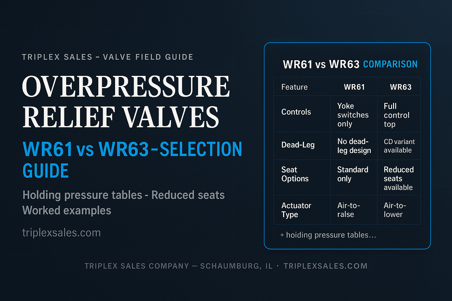
WR61 vs. WR63: Which Do You Need?
The two main options in the WR-series are the WR61 and WR63. They share the same purpose but differ in important ways that affect which one fits your application.
WR61
- Air-to-raise adjustable spring actuator
- Dead-leg body style by default (the “-T” suffix designates dead-leg models)
- No reduced seat option — select valve size to hit pressure target
- Cannot mount a control top; yoke switches only
- Simpler, lower-cost configuration
WR63
- Air-to-lower adjustable spring actuator
- WR63-CD variant eliminates dead-leg; standard WR63 includes dead-leg
- Reduced seat option available (e.g., 3″ ported valve with 2″ seat)
- Can mount a full control top with solenoids and position feedback
- Higher pressure holding capability in reduced seat configuration
The reduced seat option on the WR63 is worth understanding. Installing a smaller seat in a larger-ported valve body significantly increases the achievable holding pressure. A 3″ ported WR63 with a 2″ seat, for example, can achieve much higher relief pressure than the same body with a 3″ seat — allowing you to use a larger valve body while still hitting a tight pressure target.
Adjustment and Reseating: What the Specs Don’t Always Explain
Neither valve is factory-set. Both must be adjusted on-site using the procedure in the standard W60 IOM, which includes a chart showing PSI change per number of turns on the adjustment screw. A few things to know before you get on-site:
Field calibration is required — valves are not factory-set
WR60/WR80 series valves are not pre-set to a specific cracking pressure at the factory. Once installed, the valve must be adjusted and calibrated to the desired relief pressure and verified using a line pressure gauge. Plan for this step during commissioning.
Set range: 0 psi to max spring holding pressure
The actuator is adjustable across the full spring range — from fully unloaded (zero) to the maximum published holding pressure for that actuator size. A Positive-Stop feature prevents spring overloading and locks the setting once you’ve dialed in your target. Reference DS-1224 for holding pressure charts by actuator model and valve size.
Account for post-relief pressure rise
Once the valve actuates, the spring will produce some additional pressure drop as the valve opens further. This is documented in DS-1207. Factor it in when setting your target relief pressure.
Plan for reseating pressure
Line pressure must drop approximately 20 psi below the relief pressure setting before the valve will reseat. If your system pressure recovers slowly, the valve will stay open longer than you might expect.
Handle the adjustable actuator with care
These actuators are welded shut — they’re not maintainable. Be careful when rotating the stem during adjustment. Overtorquing can damage the internal mechanism.
Worked Example 1: Small Pump, Simple Application
Application: U2-030 pump with 1.5″ ports. Operating pressure 150 psi, relief setpoint 200 psi. Customer wants to relieve back to balance tank.
Selection process: Open DS-1201 and navigate to the WR61 holding pressure charts. The requirement is 1.5″ port size at 200 psi. Cross-reference the actuator options for that valve size.
Result: Select WR61-T, 1.5″ x 1.5″ with 5RHAR actuator. The 5RHAR (5″ air-to-raise, heavy-duty, spring adjustable) holds 378 psi at 1.5″ — well above the 200 psi setpoint, with the adjustable spring letting you dial in exactly where you want it. No controls needed, so WR61 is the simpler and correct choice. The dead-leg body style is acceptable here since flow is returning to balance tank.
Worked Example 2: Large Pump, Full Controls Required
Application: U2-180 pump with 3″ ports. Operating pressure 200 psi, relief setpoint 250 psi. Customer requires no dead-leg and wants a control top with solenoids and position feedback.
Selection process: WR63 is required (controls and WR63-CD for no dead-leg). Open DS-1201 WR63 holding pressure charts. A full 3.0″ seat on a 3″ WR63 won’t reach 250 psi with the standard actuator — well short of our target. Open DS-1224 for reduced seat options.
Result: Select WR63-CD, 3.0″ body with 2.0″ reduced seat and 6RHAL actuator. When sizing the actuator, reference the 2.0″ seat row in DS-1224 — not the 3.0″ body — since holding pressure is calculated against the reduced seat area. The WR63 uses an air-to-lower (AL) actuator; the 6RHAL holds 323 psi at the 2.0″ seat, clearing 250 psi with margin. (The 5HAL falls short at 244 psi — confirm actuator type before ordering.) The adjustable spring lets you set the relief point precisely on-site.
Quick Reference
- ▪WR61: air-to-raise, dead-leg body, yoke switches only, no reduced seats
- ▪WR63: air-to-lower, can mount control tops, reduced seats available (WR63-CD = no dead-leg)
- ▪Neither valve is factory-set — customer sets on-site
- ▪Adjustment procedure: W60 IOM
- ▪Holding pressure charts & reduced seat specs: DS-1224
- ▪Seat options: Tef-Flow™ P (std, 280°F max) or Metal (375°F max, high-flow/large particulate)
- ▪CIP: actuator piston bypasses relief setting for full open — no need to over-pressurize
- ▪Post-relief pressure rise data: DS-1207
- ▪Reseating: line pressure must drop ~20 psi below setpoint
Sizing Mistakes to Avoid
The most common error we see is selecting a valve by port size match alone. If the pump has 3″ ports, the instinct is to order a 3″ WR63 — but as the example above shows, a 3″ seat on a 3″ body may not come close to the holding pressure you need. Always size by pressure requirement first, then confirm the port size works for flow.
The second common mistake is forgetting to account for the 20 psi reseating differential. In systems where pressure recovers quickly after a relief event, this usually isn’t an issue. But in systems with long pipe runs or slow-acting downstream valves, the relief valve may stay open significantly longer than expected — which can matter for product loss calculations or CIP sequencing.
Overpressure relief valve selection is one of those areas where reading the charts carefully and using the right reference documents — DS-1201, DS-1207, DS-1224, and the W60 IOM — makes all the difference. If you’re working through an application that has unusual pressure requirements or needs a control top, reach out to your Triplex representative or contact SPX Flow Applications Engineering directly.
Questions about relief valve selection or sizing for your application?
Talk to a Triplex specialist →
